Key Specifications / Features
Model No.: SJ-DP-01 Hits: 140
Detail Information
Summary of pneumatic air operated diaphragm pump
QBY pneumatic air operated diaphragm pump is the one of the most innovative pump. For all kinds of corrosive liquid, with particles, high viscosity, volatile, flammable, explosive, poisonous liquid, ceramic glaze thick liquid, fruit purees, glue, oil tankers under-bin liquids such as oil recovery, temporary inverted cans can be smoked light. Pump body flow components material adopt stainless steel, aluminum alloy, cast iron, the diaphragm according to different liquid eyes using butyl rubber, fluorine rubber, neoprene, and four kinds of ptfe. QBY pneumatic diaphragm pumps, the use of compressed air, steam, industrial waste gas for power supply, 7 m, suction head 0 to 50 m, flow rate of 0.8-30 m3 / h stepless adjustable.
QBY pneumatic air operated diaphragm pumps series is the one of the most innovative pump. Using compressed air as power source, for all kinds of corrosive liquid, with particles of liquid, high viscosity, volatile, flammable, poisonous liquid, it can be smoked light. Its performance parameters with the Germany's WLLDENPVMPS and USA's MARIOWPUMPS.
The material of pneumatic air operated diaphragm pump
There are four kinds of material are available for the diaphragm pump: fluorine plastic, stainless steel, cast iron, aluminum alloy. Diaphragm pump according to different liquid medium with NBR, chloroprene rubber, fluorine rubber, poly (vinylidene fluoride, poly vinyl hexagon. In order to meet the needs. Housed in a variety of special occasions, cannot be used for pumping of conventional pump suction of medium.
The performance parameters of pneumatic air operated diaphragm pump
| Model | Flow (m 3 /h) |
Head (m) |
Discharge pressure (kgf/cm 2) |
Suction (m) |
Max solid size (mm) |
Max air supply (kbf/cm 2) |
| QBY-10 | 0~0.8 | 0~50 | 5 | 5 | 1 | 7 |
| QBY-15 | 0~1 | 0~50 | 5 | 5 | 1 | 7 |
| QBY-25 | 0~2.4 | 0~50 | 5 | 7 | 2.5 | 7 |
| QBY-40 | 0~8 | 0~50 | 5 | 7 | 4.5 | 7 |
| QBY-50 | 0~12 | 0~50 | 5 | 7 | 8 | 7 |
| QBY-65 | 0~16 | 0~50 | 5 | 7 | 8 | 7 |
| QBY-80 | 0~24 | 0~50 | 5 | 7 | 10 | 7 |
| QBY-100 | 0~30 | 0~50 | 5 | 7 | 10 | 7 |
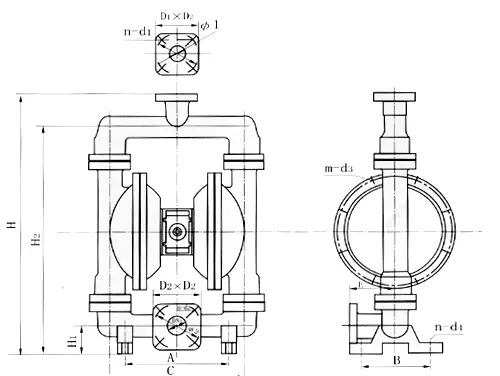
Installation dimensions chart

Model |
A | B | C | D | E | H1 | H2 | H3 | H | Screw |
Flange |
|||||
| NPT/RC | D1 | D2 | D3 | D | n | d | ||||||||||
| QBY-10 | 135 | 48 | 218 | 144 | 12 | 34 | 176 | 10 | 226 | 1/2 | - | - | - | - | - | - |
| QBY-15 | 135 | 48 | 218 | 144 | 12 | 34 | 176 | 10 | 226 | 1/2 | - | - | - | - | - | - |
| QBY-25 | 236 | 145 | 381 | 248 | 12 | 46 | 344 | 18 | 412 | 1 | - | - | - | - | - | - |
| QBY-40 | 236 | 145 | 381 | 248 | 12 | 50 | 348 | 18 | 428 | 11/2 | - | - | - | - | - | - |
| QBY-50 | 320 | 220 | 518 | 347 | 14 | 50 | 521 | 27 | 609 | 2 | 84 | 50 | 125 | 165 | 4 | 18 |
| QBY-65 | 320 | 220 | 518 | 347 | 14 | 50 | 521 | 27 | 609 | 21/2 | 104 | 65 | 145 | 185 | 4 | 18 |
| QBY-80 | 360 | 240 | 634 | 455 | 18 | 96 | 696 | 50 | 842 | 3 | 118 | 80 | 160 | 200 | 8 | 18 |
| QBY-100 | 360 | 240 | 634 | 455 | 18 | 130 | 721 | 60 | 960 | - | 140 | 100 | 180 | 200 | 8 | 18 |

