HOW YOU CAN SELECT CONTROL VALVES II
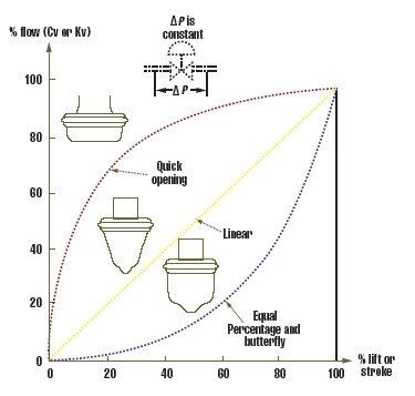
The characteristic curves were attracted, presuming the pressure drop with the valves remains constant as the valves throttle. The 3 valve characteristics vary from one another within their gain characteristics.
The gain of the control valve may be the ratio between your change (=%) within the control signal, that the valve receives and also the resulting change (=%) within the flow with the valve. Therefore, the valve gain (Gv) could be expressed as GPM/% stroke. The gain (Gv = GPM/%) of the straight line valve is constant, the gain of the equal percentage (=%) valve is growing in a constant slope, and also the gain of the quick opening (QO) valve is shedding because the valve opens.
The valve characteristics are known as straight line (straight line in Figure 1), when the gain is constant (Gv=1), and single percent alternation in the valve lift (control signal) leads to exactly the same amount (GPM) of alternation in the flow with the valve, regardless of how open the valve is. This transformation may be the slope from the straight line in Figure 1, also it can be expressed like a number of maximum flow per single percent alternation in the lift, or like a flow volume of say 5 GPM per % lift, regardless of how open the valve is.

FIGURE 1: VALVE CHARACTERISTICS
The most typical control valve characteristics for common applications.
If your 1% alternation in the valve stroke leads to exactly the same percentage change (not quantity, but % from the flow that's occurring!), then your valve characteristic is known as an equal percentage (=%). When the valve characteristics are =%, the quantity of alternation inflow is really a small quantity, once the valve is almost closed, also it becomes bigger and bigger because the valve opens.
As proven in Figure 1, in a situation of quick opening (QO) valves, the alternative may be the situation at the outset of the stroke, the valve gain is high (the flow increases in a fast slope) and towards the full opening, the slope is small.
Obtain the latest trends and enhancements in level and flow technologies
The suggested selection of the valve characteristic is really a purpose of the applying. For common applications, the advice is tabulated at the end of Figure 1. It ought to be noted that Figure 1's valve characteristics think that the valve pressure drop is constant. Regrettably, in many applications, it is not constant but drops off because the load (flow) increases. For this reason, the valve characteristics suggested in Figure 1 will vary if the number of maximum to minimum pressure differential over the valve is below or above 2:1.
One method of characterizing an analog control signal would be to insert whether divider or perhaps a multiplier into the signal line. By modifying the zero and span, an entire group of curves could be acquired. A divider can be used to transform an aura-to-open, equal-percentage valve right into a straight line one, or perhaps an air-to-close straight line valve into the same-percentage one. A multiplier can be used to transform an aura-to-open straight line valve into the same percentage, or perhaps an air-to-close equal-percentage valve into straight line one.
Distortion of Valve Characteristics
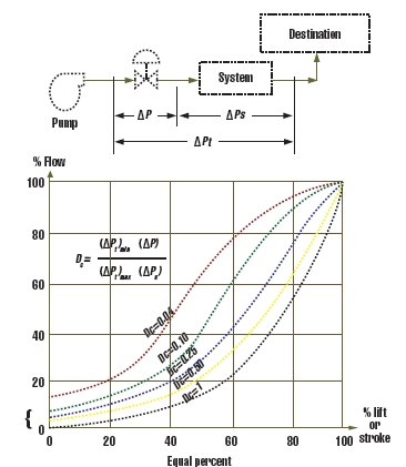
Figure 2 below shows the result from the distortion coefficient (Electricity, defined in Figure 2) around the characteristics of the =% valve. As the number of the minimum to maximum pressure drop increases, the Electricity coefficient drops and also the =% characteristics from the valve shifts towards a straight line.

FIGURE 2: DISTORTION COEFFICIENT
The characteristic curve of the equal percentage valve shifts towards straight line because the Distortion Coefficient (Electricity) drops. This drop also cuts down on the rangeability from the valve.
Similarly, under the conditions, the options of the straight line valve would shift towards quick opening (QO, not proven in Figure 2). Additionally, because the Electricity coefficient drops, the controllable minimum flow increases, and then the "rangeability" from the valve also drops.
Rangeability
The traditional meaning of rangeability may be the ratio between your maximum and minimum "controllable" flows with the valve. Minimum controllable flow (Fmin) isn't the leakage flow (which takes place when the valve is closed), however the minimum flow that's still controllable, and could be altered up or lower because the valve is throttled.
By using this definition, manufacturers usually claim a 50:1 rangeability for equal-percentage valves, 33:1 for straight line valves, contributing to 20:1 for convenient-opening valves. These claims claim that the flow with these valves could be controlled lower to two percent, 3%, and 5% of maximum. However, these figures are frequently exaggerated. Additionally, as are visible in Figure 2, the minimum controllable flow (Fmin) increases because the distortion coefficient (Electricity) drops. Therefore, in an Electricity of .1, the 50:1 rangeability of the equal-percentage valve drops to around 10:1.
Consequently, the rangeability ought to be understood to be the flow range that the particular installed valve gain stays within ±25% from the theoretical (natural) valve gain (within the units of GPM per % stroke). As one example of the significance of this limitation, Figure 3 shows the particular gain of the equal percentage valve begins to deviate from the theoretical gain by greater than 25%, once the flow reaches about 65%.
Therefore, in figuring out the rangeability of these a valve, the utmost allowable flow ought to be 65%. Really, if a person makes use of this definition, the rangeability of the =% valve is rarely greater than 10:1. In such instances, the rangeability of the straight line valve could be more than those of a =% valve. Also, the rangeability of some rotary valves could be greater as their clearance flow is commonly lower, as well as their body losses close to the available position also are usually less than individuals of other valve designs.
To remain within ±25% from the theoretical valve's gain, the utmost flow shouldn't exceed 60% of the maximum inside a straight line valve or 70% within a =% valve. When it comes to valve lift, these flow limits match 85% of maximum lift for =% and 70% for straight line valves.